


Vibration Damping
Damping Concepts:
Complex modulus expressed in terms
of the storage modulus (real) and loss
modulus (imaginary)
Complex modulus expressed in terms
of the storage modulus (real) and loss
modulus (imaginary)
The storage modulus represents
non-dissipative elastic energy;
whereas, the loss modulus represents
dissipative thermal energy.
non-dissipative elastic energy;
whereas, the loss modulus represents
dissipative thermal energy.
The ratio of imaginary to real terms is
defined as the tan delta, or loss factor
defined as the tan delta, or loss factor

Viscoelastic Behavior:
A viscoelastic solid exhibits a
phase lag between the strain
and corresponding stress.
Recall, that for a linear elastic
solid, the stress and strain
remain in phase.
Hookean, or linear, elastic
solids, have the ability to store
energy under load; however,
they cannot dissipate energy.
Newtonian fluids can dissipate
energy, but cannot store it.
Viscoelastic materials, have the
ability to store and dissipate
energy.

| Viscoelastic Solid |
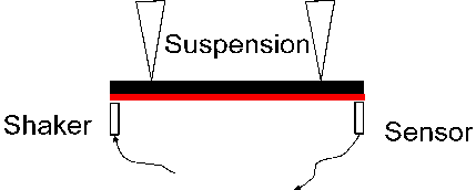
Measuring Damping Material Properties
| When evaluating vibration damping performance one may review several publicly available standards. For example, ASTM E756 Standard Test Method for Measuring Vibration-Damping Properties of Materials, SAE J1637 Laboratory Measurement of the Composite Vibration Damping Properties of Materials on A Supporting Steel Bar, and ISO 6721-3 Determination of dynamic mechanical properties Part 3: Flexural vibration-Resonance-curve method If your objective is to compare two or more damping treatments you may want use the method outlined in SAEJ1637. However, if your goal is to evaluate damping material alone you should follow the ASTME756 or the ISO 6721-3methods. |
General tips to measure material properties
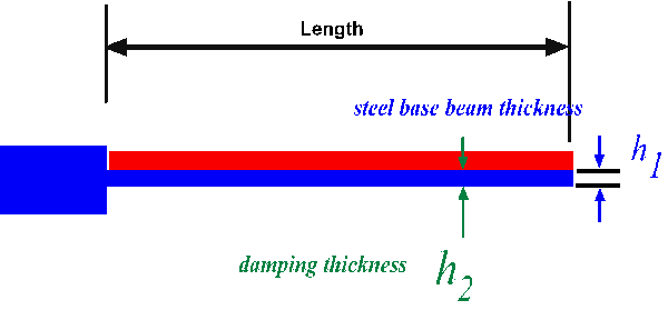
A common technique used to measure damping properties employs the so called Oberst Bar. The Obesrt bar is
damped on one side; while the modified Oberst bar is damped on two sides. To measure the material properties,
one measures the modal system loss factors of the Oberst bar at various temperatures.
The Oberst and Modified Oberst beam facilitates damping measurements of non-self supporting materials. This
technique is valid for extensional, or single layer treatments if the modulus is relatively stiff.
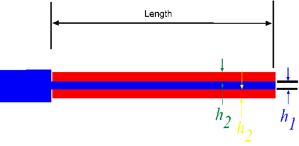
| Oberst Bar |
| Modified Oberst Bar |
Determining material damping properties using the beam method relies on the measured
differences of a damped beam and an untreated, or base, beam. This technique is limited to
small differences in large numbers. Thus, small experimental errors may result in large
arithmetic errors in when calculating damping properties.
To avoid ill-conditioned equations you have three parameters to control:
If your damping treatment is too thick the system may be overdamped; thus you will have
difficulty in achieving adequate signals. By judiciously selecting various base beam
thicknesses and lengths you can design a system to adequately measure the composite loss
factor and have well conditioned equations to compute the material properties. I recommend
that you refer to ASTME756 Section 5.4 Precautions for further guidance.
differences of a damped beam and an untreated, or base, beam. This technique is limited to
small differences in large numbers. Thus, small experimental errors may result in large
arithmetic errors in when calculating damping properties.
To avoid ill-conditioned equations you have three parameters to control:
- Base beam thickness
- Base beam length
- Damping treatment thickness
If your damping treatment is too thick the system may be overdamped; thus you will have
difficulty in achieving adequate signals. By judiciously selecting various base beam
thicknesses and lengths you can design a system to adequately measure the composite loss
factor and have well conditioned equations to compute the material properties. I recommend
that you refer to ASTME756 Section 5.4 Precautions for further guidance.
Environmental Test Conditions
It is necessary to measure damping properties at various frequencies and
temperatures. However, note that Plasticization of polymers by absorbed moisture
results in a reduced glass transition temperature.
temperatures. However, note that Plasticization of polymers by absorbed moisture
results in a reduced glass transition temperature.
Composite Loss Factor and Material Loss Factor
The relationship between the material loss factor is given below:
where,
Thus, the composite loss factor is proportional to thickness ratio, material loss factor, and
modulus ratio. Note however, For the same polymeric content, the composite loss may be
increased by applying more material. Mathematically, the composite loss factor converges to
the material loss factor for a 10:1 ratio of damping thickness to substrate thickness.
Practically, thick material applications prohibit solvent evaporation and performance
degradation. Furthermore, the opportunity cost of thick damping treatments include system
weight.
However, if the thickness is increased by foaming the density decreases and the composite
loss factor increases with out an increase in weight of polymer content.
Temperature-Frequency Nomogram
The ISO method offers an alternative test method
using free-free (approximate) boundary conditions. As
shown below:
using free-free (approximate) boundary conditions. As
shown below: